
Combination of Inductors, LR & LC Circuits
By combining three inductances, H, H and H, the minimum value of effective inductance that can be obtained is (in H)
Show answer and solution
Answer: (a)
Loading the solution…
Home›Practice Hub›Chapters›Electromagnetic Induction›Combination of Inductors, LR & LC Circuits
Electromagnetic Induction PYQs · MHT CET · JEE Main · NEET
Combination of Inductors, LR & LC Circuits
By combining three inductances, H, H and H, the minimum value of effective inductance that can be obtained is (in H)
Answer: (a)
Combination of Inductors, LR & LC Circuits
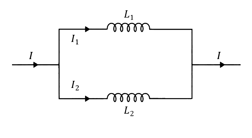
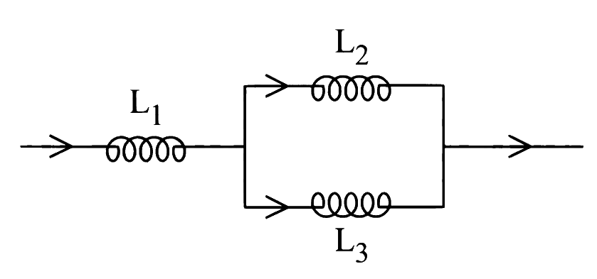
Two inductors, and are connected in parallel and a time varying current flows as shown in the figure. The ratio of currents at any time, it is
Answer: (b)
Combination of Inductors, LR & LC Circuits
Two inductors, and , are connected in parallel and time-varying current flows the combination. If and are the currents passing through the inductor and respectively, the ratio is
Answer: (b)
Combination of Inductors, LR & LC Circuits
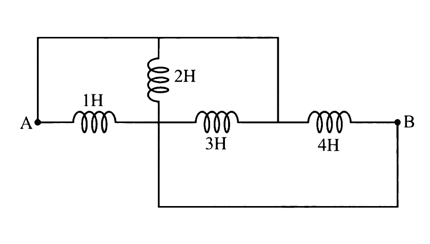
The equivalent inductance between A and B is equal to
Answer: (c)
Combination of Inductors, LR & LC Circuits
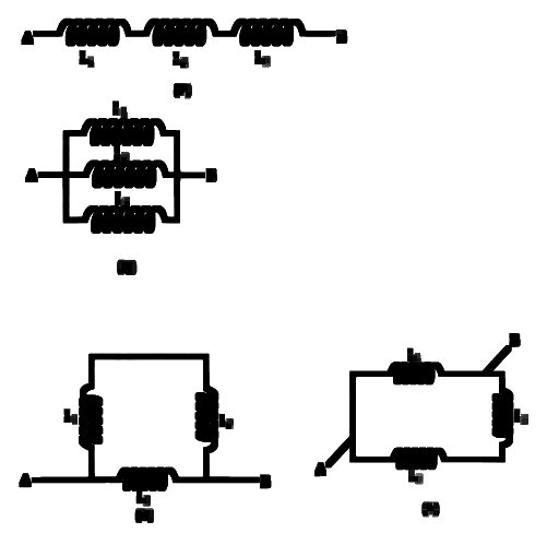
Three coils of inductance, = 2 H, = 3 H and = 6 H are connected so that they are separated from each other. To obtain the effective inductance of H between points A and B, out of the following figures, the correct one is
Answer: (b)
Combination of Inductors, LR & LC Circuits
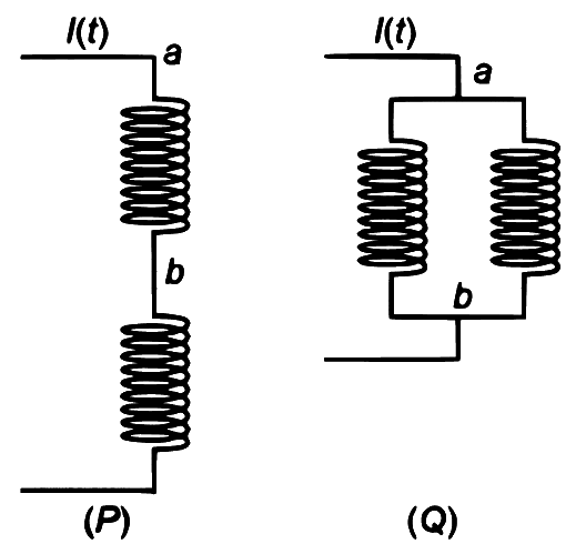
Two identical inductors are connected in two different configurations and , where a time varying current is flowing, as shown in the figure. The induced emf between points and for configuration is and that for configuration is . The ratio is:
[Neglect the effect of mutual inductance.]
Answer: (a)
Combination of Inductors, LR & LC Circuits
In the given circuit, if A/s then the value of at this instant will be
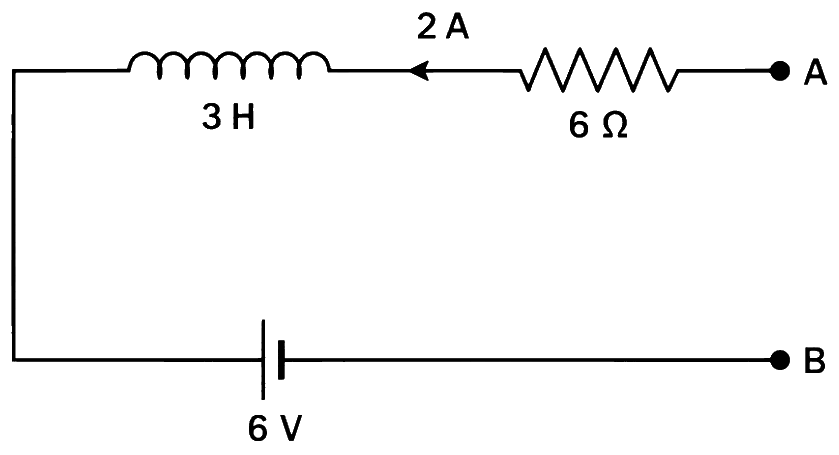
Answer: (d)
Combination of Inductors, LR & LC Circuits
The following figure represents two bulbs and , resistor R and an inductor L. When the switch S is turned off, which of the following statement is true?
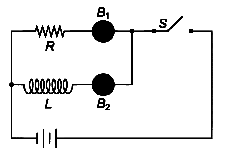
Answer: (c)
Combination of Inductors, LR & LC Circuits
An inductor of inductance 10 mH having resistance of is connected to battery of E.M.F. 1.0 V through a switch as shown in the figure below. After switch is closed, the ratio of instantaneous voltages across the inductor when the current passing through it is 2 mA and 4 mA is ______.
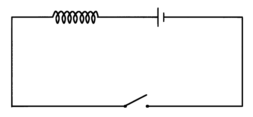
Answer: (a)
Combination of Inductors, LR & LC Circuits
Figure shows the circuit that contains three resistances ( each) and two inductors ( 4 mH each). The reading of ammeter at the moment switch is turned ON, is ______ A.
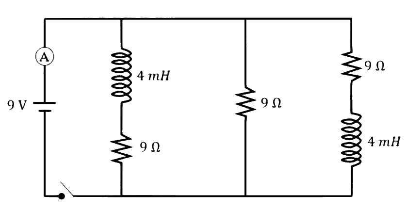
Answer: (c)
Combination of Inductors, LR & LC Circuits
In the given circuit below inductance values of and are same. The magnetic energy stored in the entire circuit is and that stored in the inductor is is ______. (Ignore the mutual inductance if any)
Numerical answer type. Work it out, then open the answer.
Answer: 6
Combination of Inductors, LR & LC Circuits
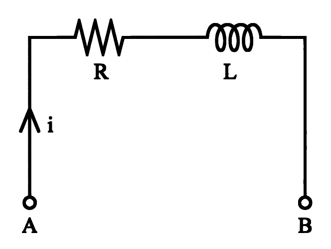
In the circuit shown, when the current '' is A and increasing at the rate of A/s the measurement of the potential difference between A and B is V. But when the same current A is decreasing at the rate of A/s, the measured potential difference between A and B is V. The value of 'R' in the circuit is
Answer: (a)
Combination of Inductors, LR & LC Circuits
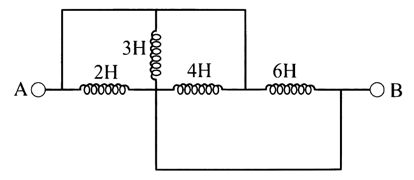
The equivalent inductance between A and B is equal to
Answer: (a)
Combination of Inductors, LR & LC Circuits
Two identical coils of inductance joined in series are placed very close to each other such that the winding direction of one coil is exactly opposite to that of the other. The net inductance is
Answer: (c)
Combination of Inductors, LR & LC Circuits
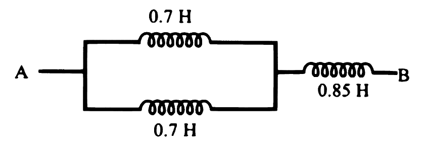
Three inductances are connected as shown in the figure. The equivalent inductance between A and B is
Answer: (b)
Combination of Inductors, LR & LC Circuits
is a part of an electrical circuit (see figure). The potential difference " ", at the instant when current and is increasing at a rate of second is:

Answer: (b)
Combination of Inductors, LR & LC Circuits
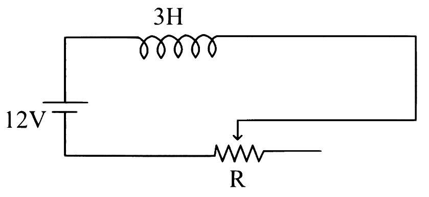
In the given circuit the sliding contact is pulled outwards such that electric current in the circuit changes at the rate of . At an instant when R is , the value of the current in the circuit will be ________ A.
Numerical answer type. Work it out, then open the answer.
Answer: 3
Combination of Inductors, LR & LC Circuits
An inductor coil of inductance is divided into two parts and both parts are connected in parallel. The net inductance is
Answer: (d)
Combination of Inductors, LR & LC Circuits
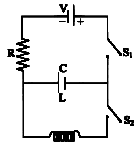
Consider the following circuit. By keeping closed, the capacitor is fully charged and then is opened and is closed, then
Answer: (d)
Combination of Inductors, LR & LC Circuits
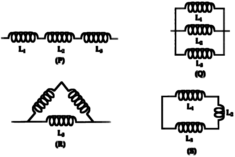
Three coils of inductance and are connected such that they are separated from each other. To obtain the effective inductance of 1 henry, out of the following combinations as shown in figure, the correct one is
Answer: (d)
Combination of Inductors, LR & LC Circuits
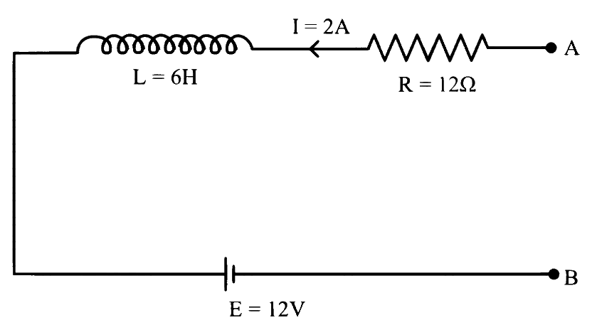
As per the given figure, if then the value of at this instant will be ____________ .
Numerical answer type. Work it out, then open the answer.
Answer: 30
Combination of Inductors, LR & LC Circuits
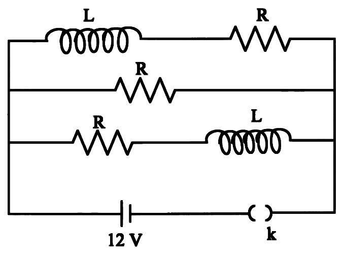
Three identical resistors with resistance R = 12 and two identical inductors with self inductance L = 5 mH are connected to an ideal battery with emf of 12 V as shown in figure. The current through the battery long after the switch has been closed will be _____________ A.
Numerical answer type. Work it out, then open the answer.
Answer: 3
Combination of Inductors, LR & LC Circuits
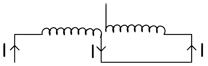
Two coils of self inductance L1 and L2 are connected in series combination having mutual inductance of the coils as M. The equivalent self inductance of the combination will be:
Answer: (d)
Combination of Inductors, LR & LC Circuits
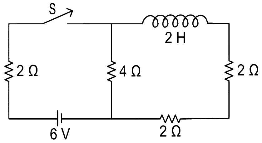
For the given circuit the current through battery of 6 V just after closing the switch 'S' will be _________ A.
Numerical answer type. Work it out, then open the answer.
Answer: 1
Combination of Inductors, LR & LC Circuits
An inductor coil stores 64 J of magnetic field energy and dissipates energy at the rate of 640 W when a current of 8A is passed through it. If this coil is joined across an ideal battery, find the time constant of the circuit in seconds:
Answer: (d)
Combination of Inductors, LR & LC Circuits
The time taken for the magnetic energy to reach 25% of its maximum value, when a solenoid of resistance R, inductance L is connected to a battery, is:
Answer: (c)
Combination of Inductors, LR & LC Circuits
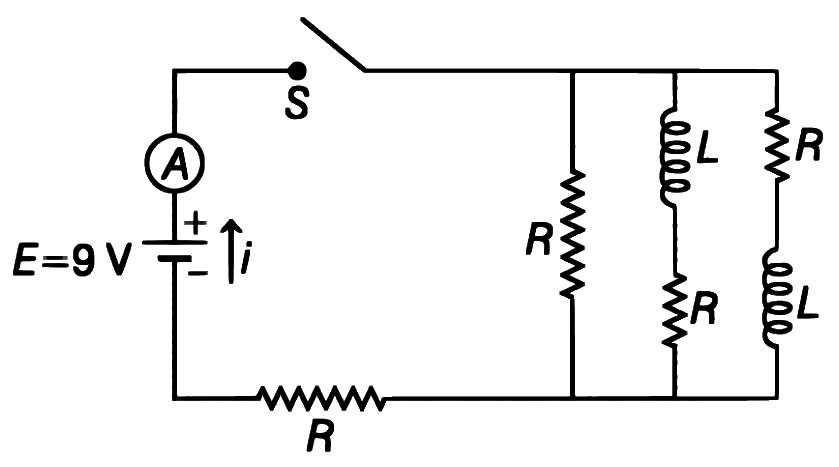
Figure shows a circuit that contains four identical resistors with resistance R = 2.0, two identical inductors with inductance L = 2.0 mH and an ideal battery with emf E = 9V. The current 'i' just after the switch 'S' is closed will be:
Answer: (d)
Combination of Inductors, LR & LC Circuits
A circuit has self-inductance 'L' H and carries a current 'I' A. To prevent sparking when the circuit is switched off, a capacitor which can withstand 'V' volt is used. The least capacitance of the capacitor connected across the switch must be equal to
Answer: (c)
Combination of Inductors, LR & LC Circuits
A part of a complete circuit is shown in the figure. At some instant, the value of current I is 1A and it is decreasing at a rate
of 102 A s–1. The value of the potential difference VP – VQ, (in volts) at that instant, is _________.

Numerical answer type. Work it out, then open the answer.
Answer: 33
Combination of Inductors, LR & LC Circuits
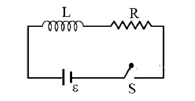
A shown in the figure, a battery of emf is connected to an inductor L and resistance R in series. The switch is closed at t = 0. The total charge that flows from the battery, between t = 0 and t = tc (tc is the time constant of the circuit) is:
Answer: (a)
Combination of Inductors, LR & LC Circuits
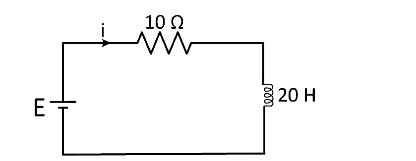
A 20 Henry inductor coil is connected to a 10 ohm resistance in series as shown in figure. The time at which rate of dissipation of energy (joule's heat) across resistance is equal to the rate at which magnetic energy is stored in the inductor is:
Answer: (c)
Combination of Inductors, LR & LC Circuits
An ideal coil of is connected in series with a resistance of and a battery of second after the connection is made, the current flowing in ampere in the circuit is
Answer: (a)
Combination of Inductors, LR & LC Circuits
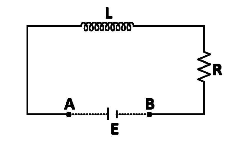
An inductor , a resistor and a battery are initially connected in series as shown in the figure. After a long time the battery is disconnected after short circuiting the points and . The current in the circuit after the short circuit is
Answer: (a)
Combination of Inductors, LR & LC Circuits
A coil of inductance and resistance is connected to a source of voltage . The current reaches half of its steady state value in
Answer: (a)
Combination of Inductors, LR & LC Circuits
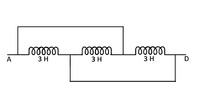
The inductance between and is
Answer: (d)
No questions match these filters.