Alternating Current PYQs · MHT CET · JEE Main · NEET
Inductors & DC Transients (Mixed)
Questions
32
MHT CET
6
JEE Main
20
NEET
6
Years
1999–2026
0 of 32 attemptedPick an answer to see the solution
Q1MHT CET 2026 · 19 APR · SHIFT 2Medium
Inductors & DC Transients (Mixed) · Inductor energy and combinations
Two coils P and S have a mutual inductance of (π) mH. The secondary coil S has resistance 4Ω and self inductance (60/π) mH. If the current in the primary is Ip=12sin(50πt), then the maximum value of the current induced in coil S is [Take π2=10]
Inductors & DC Transients (Mixed) · Inductor energy and combinations
A coil has an inductance of 2 H and resistance of 4Ω. A 10 V is applied across the coil. The energy stored in the magnetic field after the current has built up to its equilibrium value will be ___________ ×10−2 J.
Numerical answer type. Work it out, then open the answer.
Inductors & DC Transients (Mixed) · LR and RC circuits on DC
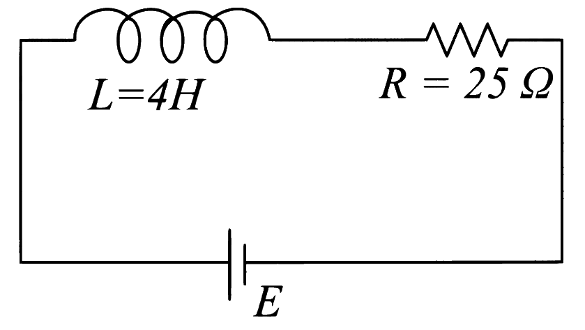
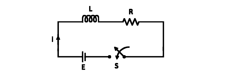
In the given figure, an inductor and a resistor are connected in series with a battery of emf E volt. 2bEa J/s represents the maximum rate at which the energy is stored in the magnetic field (inductor). The numerical value of ab will be __________.
Numerical answer type. Work it out, then open the answer.
Inductors & DC Transients (Mixed) · LR and RC circuits on DC
A coil of inductance 1 H and resistance 100Ω is connected to a battery of 6 V. Determine approximately:
(a) The time elapsed before the current acquires half of its steady - state value.
(b) The energy stored in the magnetic field associated with the coil at an instant 15 ms after the circuit is switched on. (Given ln2=0.693,e−3/2=0.25)
Inductors & DC Transients (Mixed) · LR and RC circuits on DC
An inductor of 10 mH is connected to a 20V battery through a resistor of 10 kΩ and a switch. After a long time, when maximum current is set up in the circuit, the current is switched off. The current in the circuit after 1 μs is 100x mA. Then x is equal to ___________. (Take e______1 = 0.37)
Numerical answer type. Work it out, then open the answer.
Inductors & DC Transients (Mixed) · Inductor energy and combinations
In the part of an a.c. circuit as shown, the resistance R=0.2Ω. At a certain instant (VA−VB)=0.5 V,I=0.5 A and ΔtΔI=8 A/s. The inductance of the coil is
Inductors & DC Transients (Mixed) · Inductor energy and combinations
An inductor coil wound uniformly has self inductance 'L' and resistance 'R'. The coil is broken into two identical parts. The two parts are then connected in parallel across a battery of 'E' volt of negligible internal resistance. The current through battery at steady state is
Inductors & DC Transients (Mixed) · LR and RC circuits on DC
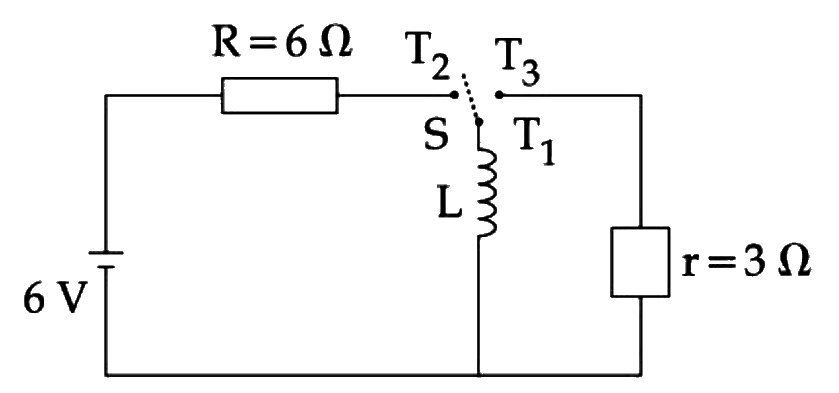
Consider an electrical circuit containing a two way switch 'S'. Initially S is open and then T1 is connected to T2. As the current in R = 6Ω attains a maximum value of steady state level, T1 is disconnected from T2 and immediately connected to T3. Potential drop across r = 3Ω resistor immediately after T1 is connected to T3 is __________ V. (Round off to the Nearest Integer)
Numerical answer type. Work it out, then open the answer.
Inductors & DC Transients (Mixed) · LR and RC circuits on DC
A series L-R circuit is connected to a battery of emf V. If the circuit is switched on at t = 0, then the time at which the energy stored in the inductor reaches (n1) times of its maximum value, is:
Inductors & DC Transients (Mixed) · LR and RC circuits on DC
An emf of 20 V is applied at time t = 0 to a circuit containing in series 10 mH inductor and 5 Ω resistor. The ratio of the currents at time t = ∞ and at t = 40 s is close to: (Take e2 = 7.389)
Inductors & DC Transients (Mixed) · LR and RC circuits on DC
A coil of self inductance 10 mH and resistance 0.1 Ω is connected through a switch to a battery of internal resistance 0.9 Ω. After the switch is closed, the time taken for the current to attain 80% of the saturation value is: [take ln 5 = 1.6]
Inductors & DC Transients (Mixed) · LR and RC circuits on DC
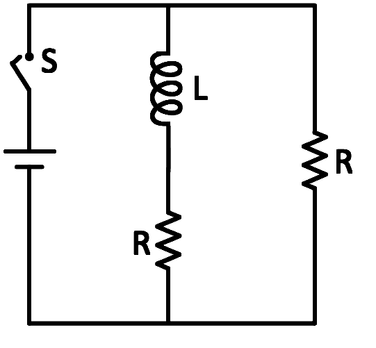
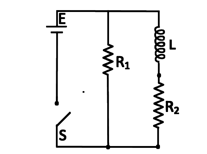
In the figure shown, a circuit contains two identical resistors with resistance R = 5Ω and an inductance with L = 2mH. An ideal battery of 15 V is connected in the circuit. What will be the current through the battery long after the switch is closed?
Inductors & DC Transients (Mixed) · LR and RC circuits on DC
Consider the LR circuit shown in the figure. If the switch S is closed at t = 0 then the amount of charge that passes through the battery between t = 0 and t = RL is:
Inductors & DC Transients (Mixed) · LR and RC circuits on DC
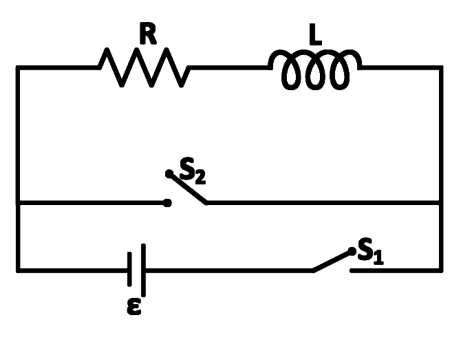
In the circuit shown,
the switch S1 is closed at time t = 0 and the switch S2 is kept open. At some later time(t0), the switch S1 is opened and S2 is closed. The behavior of the current I as a function of time 't' is given by:
Inductors & DC Transients (Mixed) · LR and RC circuits on DC
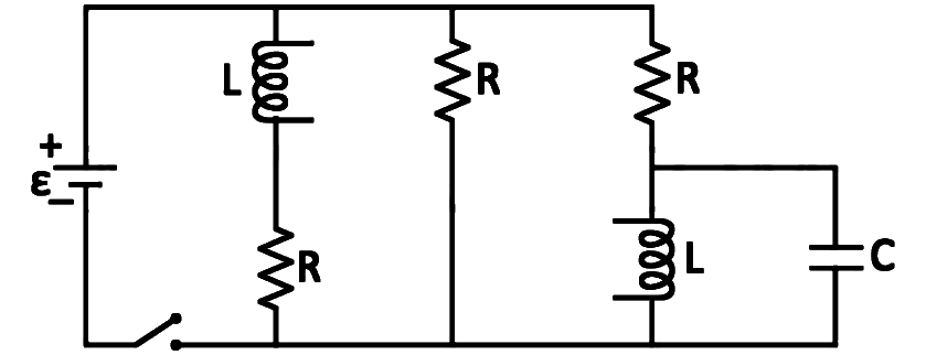
Figure shows a circuit that contains three identical resistors with resistance R = 9.0 Ω each, two identical inductors with inductance L = 2.0 mH each, and an ideal battery with emf ε=18 V. The current i through the battery just after the switch is closed is
Inductors & DC Transients (Mixed) · LR and RC circuits on DC
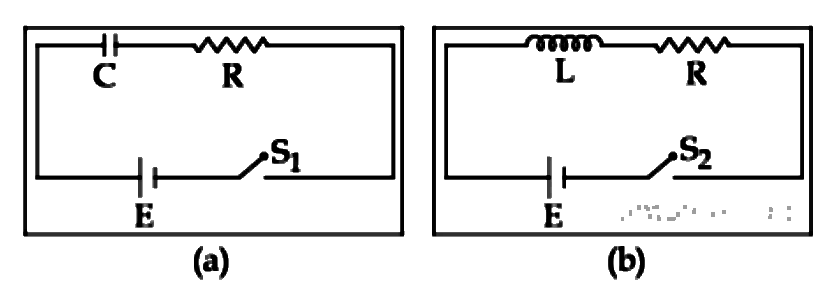
In the circuits (a) and (b) switches S1 and S2 are closed at t = 0 and are kept closed for a long time. The variation of currents in the two circuits for t ≥ 0 are roughly shown by (figures are schematic and not drawn to scale):
Inductors & DC Transients (Mixed) · LR and RC circuits on DC
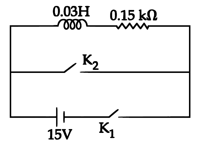
An inductor (L=0.03 H) and a resistor (R=0.15 kΩ) are connected in series to a battery of 15 VEMF in a circuit shown below. The key K1 has been kept closed for a long time. Then at t=0,K1 is opened and key K2 is closed simultaneously. At t=1 ms, the current in the circuit will be: (e5≅150)
Inductors & DC Transients (Mixed) · LR and RC circuits on DC
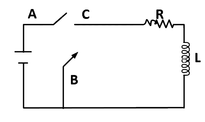
In the circuit shown here, the point ′C′ is kept connected to point ′A′ till the current flowing through the circuit becomes constant. Afterward, suddenly, point ′C′ is disconnected from point ′A′ and connected to point ′B′ at time t=0. Ratio of the voltage across resistance and the inductor at t=L/R will be equal to:
Inductors & DC Transients (Mixed) · LR and RC circuits on DC
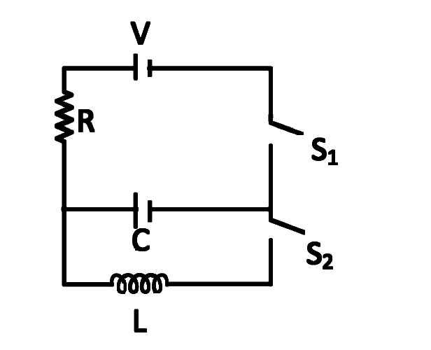
In an LCR circuit as shown below both switches are open initially. Now switch S1 is closed, S2 kept open. (q is charge on the capacitor and τ=RC is Capacitance time constant). Which of the following statements is correct?
Inductors & DC Transients (Mixed) · LR and RC circuits on DC
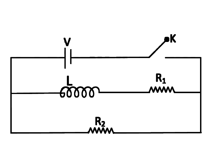
An inductor of inductance L=400 mH and resistors of resistance R1=2Ω and R2=2Ω are connected to a battery of emf 12 V as shown in the figure. The internal resistance of the battery is negligible. The switch S is closed at t=0. The potential drop across L as a function of time is:
Inductors & DC Transients (Mixed) · LR and RC circuits on DC
A coil of 40 henry inductance is connected in series with a resistance of 8 ohm and the combination is joined to the terminals of a 2 volt battery. The time constant of the circuit is
Inductors & DC Transients (Mixed) · LR and RC circuits on DC
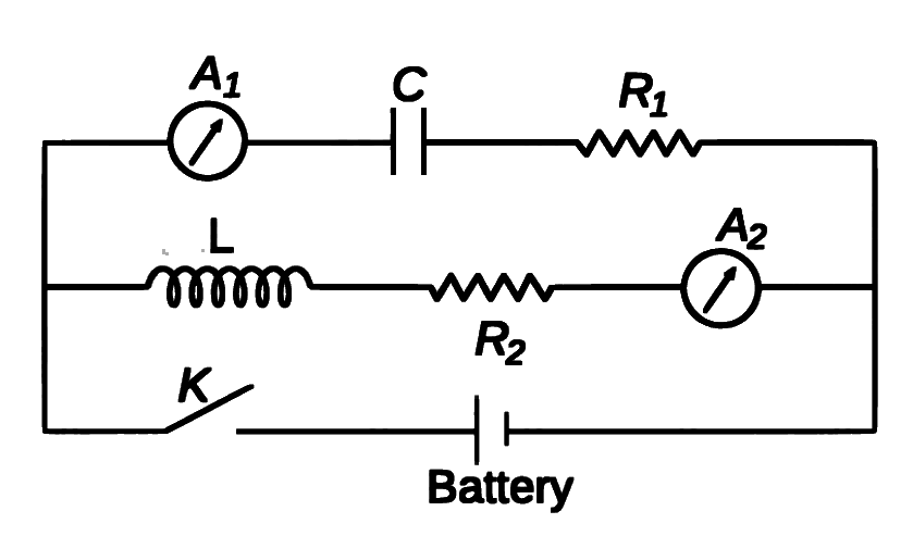
In a circuit inductance L and capacitance C are connected as shown in figure. A1 and A2 are ammeters. When key K is pressed to complete the circuit, then just after closing key (K), the reading of current will be