Alternating Current PYQs · MHT CET · JEE Main · NEET
Power, Power Factor & Wattless Current
Questions
82
MHT CET
35
JEE Main
35
NEET
12
0 of 82 attempted
Q1MHT CET 2026 · 17 APR · SHIFT 2Easy
Power, Power Factor & Wattless Current
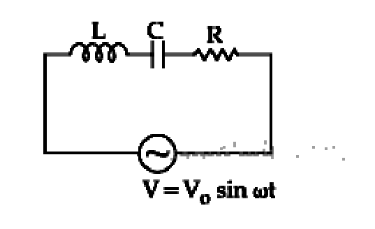
In a series LCR circuit alternating e.m.f. and current are given by the equations V=V0sin(ωt) and I=I0sin(ωt+3π) respectively. The average power dissipated in the circuit over one cycle of a.c. is (cos60∘=0.5)
In series LCR circuit, resistance is 18Ω and impedance 33Ω. An r.m.s. Voltage of 220 V is applied across the circuit. The true power consumed in a c. circuit is
A LCR series circuit driven with Erms=90 V at frequency fd=30 Hz has resistance R=80Ω, an inductance with inductive reactance XL=20.0Ω and capacitance with capacitive reactance XC=80.0Ω. The power factor of the circuit is ______.
An inductor of inductance L and a resistor of resistance R are joined in series and connected to an a.c. source of frequency ω. The power dissipated in the circuit is
An inductor of reactance 100Ω, a capacitor of reactance 50Ω, and a resistor of resistance 50Ω are connected in series with an AC source of 10 V, 50 Hz. Average power dissipated by the circuit is ____
For series LCR circuit, the current is observed to lead the applied voltage. An additional capacitor C1 when joined with capacitor C, makes the power factor of the circuit unity. The capacitor C1 must be connected in
An a.c. source is applied to a series LR circuit with XL=3R and power factor is X1. Now a capacitor with Xc=R is added in series to LR circuit and power factor is X2. The ratio X1 to X2 is
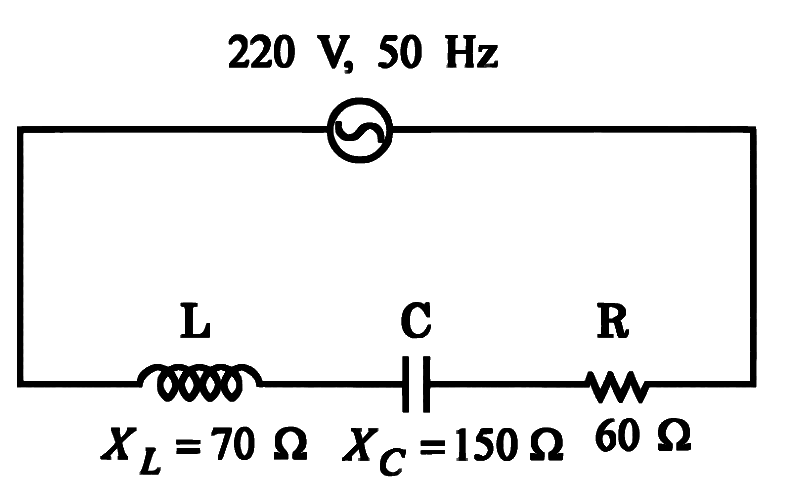
A series LCR circuit is connected to an a.c. source of 220 V, 50 Hz. The circuit contains a resistance R=80Ω, an inductor of inductive reactance 70Ω and capacitor of capacitive reactance 130Ω. The power factor of the circuit is 10x. The value of x is
In a series LR circuit with XL=R. Power factor is P1. If a capacitor of capacitance C with Xc=XL is added to the circuit the power factor becomes P2. The ratio of P1 to P2 will be:
An inductor of 10 mH, capacitor of 0.1μF and a resistor of 100Ω are connected in series across an a.c power supply 220 V,70 Hz. The power factor of the given circuit is 0.5. The difference in the inductive reactance and capacitance reactance is 3αΩ. The value of α is ______.
Numerical answer type. Work it out, then open the answer.
An arc lamp requires a direct current of 10 A at 90 V to function. If it is connected to 220 V (rms), 50 Hz a.c. supply, the series inductor needed for it to work is nearly
In LCR series circuit, R = 18 Ω and impedance 33Ω. An r.m.s. voltage of 220 V is applied across the circuit. The true power consumed in a.c. circuit is
Given below are two statements: one is labelled as Assertion (A) and the other is labelled as Reason (R).
Assertion (A): Choke coil is simply a coil having a large inductance but a small resistance. Choke coils are used with fluorescent mercury-tube fittings. If household electric power is directly connected to a mercury tube, the tube will be damaged.
Reason (R): By using the choke coil, the voltage across the tube is reduced by a factor (R/R2+ω2L2), where ω is frequency of the supply across resistor R and inductor L. If the choke coil were not used, the voltage across the resistor would be the same as the applied voltage. In the light of the above statements, choose the most appropriate answer from the options given below:
In an L−R circuit, the inductive reactance is equal to 3 times the resistance ' R ' of the circuit. An e.m.f. E=E0sin(ωt) is applied to the circuit. The power consumed in the circuit is
An inductor of reactance 100Ω, a capacitor of reactance 50Ω, and a resistor of resistance 50Ω are connected in series with an AC source of 10 V,50 Hz. Average power dissipated by the circuit is ___________ W.
Numerical answer type. Work it out, then open the answer.
An a.c. source is applied to a series LR circuit with XL=3R and power factor is X1. Now a capacitor with Xc=R is added in series to LR circuit and the power factor is X2. The ratio X1 to X2 is
In LCR series circuit, an alternating e.m.f. 'e' and current ' i ' are given by equations e=160sin(100t) Volt and i=250sin(100t+3π) mA. The average power dissipated in the circuit is
In an A.C. circuit, the potential difference ' V ' and current 'I' are given respectively by V=100sin(100t) V,I=100sin(100t+3π) mA The power dissipated in the circuit will be [Given →cos3π=21 ]
A series LCR circuit with L=π100 mH,C=π10−3 F and R=10Ω, is connected across an ac source of 220 V,50 Hz supply. The power factor of the circuit would be ________.
Numerical answer type. Work it out, then open the answer.
An e.m.f. E=E0cosωt is applied to the L−R circuit. The inductive reactance is equal to the resistance ' R ' of the circuit. The power consumed in the circuit is
A capacitor of reactance 43Ω and a resistor of resistance 4Ω are connected in series with an ac source of peak value 82 V. The power dissipation in the circuit is __________ W.
Numerical answer type. Work it out, then open the answer.
A series L.R circuit connected with an ac source E=(25sin1000t) V has a power factor of 21. If the source of emf is changed to E=(20sin2000t) V, the new power factor of the circuit will be:
Statement I: Maximum power is dissipated in a circuit containing an inductor, a capacitor and a resistor connected in series with an AC source, when resonance occurs
Statement II: Maximum power is dissipated in a circuit containing pure resistor due to zero phase difference between current and voltage.
In the light of the above statements, choose the correct answer from the options given below:
In a L-R circuit the inductive reactance is equal to the resistance R in the circuit. An emf E=E0cosωt is applied to the circuit. The power consumed in the circuit is
A series LCR circuit is connected to an AC source of 220 V, 50 Hz. The circuit contains a resistance R = 80Ω, an inductor of inductive reactance XL=70Ω, and a capacitor of capacitive reactance XC=130Ω. The power factor of circuit is 10x. The value of x is:
Numerical answer type. Work it out, then open the answer.
In a series LR circuit, XL=R, power factor is P1. If a capacitor of capacitance C with XC=XL is added to the circuit the power factor becomes P2. The ratio of P1 to P2 will be
In a series LR circuit with XL=R, power factor P1. If a capacitor of capacitance C with XC=XL is added to the circuit the power factor becomes P2. The ratio of P1 to P2 will be:
In a series LR circuit XL=R and power factor of the circuit is P1. When capacitor with capacitance C such that XL=XC is put in series, the power factor becomes P2. The ratio P2P1 is:
To light, a 50 W,100 V lamp is connected, in series with a capacitor of capacitance πx50μF, with 200 V,50 Hz AC source. The value of x will be ___________.
Numerical answer type. Work it out, then open the answer.
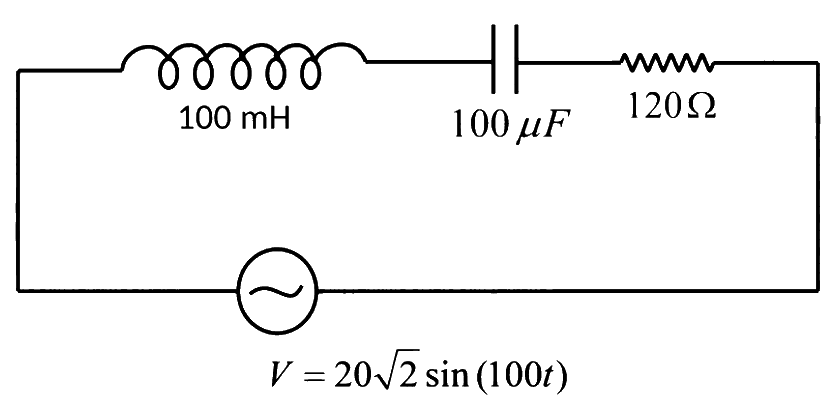
An AC source is connected to an inductance of 100 mH, a capacitance of 100 μF and a resistance of 120 Ω as shown in figure. The time in which the resistance having a thermal capacity 2 J/∘C will get heated by 16∘ C is _____________ s.
Numerical answer type. Work it out, then open the answer.
In a series LCR circuit, the inductive reactance (XL) is 10Ω and the capacitive reactance (XC) is 4Ω. The resistance (R) in the circuit is 6Ω. The power factor of the circuit is:
An ac circuit has an inductor and a resistor of resistance R in series, such that XL = 3R. Now, a capacitor is added in series such that XC = 2R. The ratio of new power factor with the old power factor of the circuit is 5:x. The value of x is ___________.
Numerical answer type. Work it out, then open the answer.
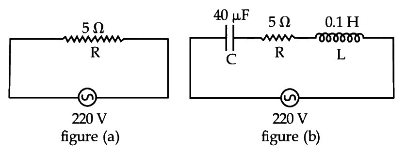
Two circuits are shown in the figure (a) & (b). At a frequency of ____________ rad/s the average power dissipated in one cycle will be same in both the circuits.
Numerical answer type. Work it out, then open the answer.
A series LCR circuit driven by 300 V at a frequency of 50 Hz contains a resistance R = 3 kΩ, an inductor of inductive reactance XL = 250 πΩ and an unknown capacitor. The value of capacitance to maximize the average power should be: (Take π2 = 10)
An LCR circuit contains resistance of 110Ω and a supply of 220 V at 300 rad/s angular frequency. If only capacitance is removed from the circuit, current lags behind the voltage by 45∘. If on the other hand, only inductor is removed the current leads by 45∘ with the applied voltage. The rms current flowing in the circuit will be:
A 750 Hz, 20 V (rms) source is connected to a resistance of 100 Ω, an inductance of 0.1803 H and a capacitance of 10 μF all in series. The time in which the resistance (heat capacity 2 J/oC) will get heated by 10oC. (assume no loss of heat to the surroudnings) is close to:
In a series LR circuit, power of 400W is dissipated from a source of 250 V, 50 Hz. The power factor of the circuit is 0.8. In order to bring the power factor to unity, a capacitor of value C is added in series to the L and R. Taking the value of C as (3πn)μF, then value of n is __________.
Numerical answer type. Work it out, then open the answer.
A series AC circuit containing an inductor (20 mH), a capacitor (120 μF) and a resistor (60 Ω) is driven by an AC source of 24V/50 Hz. The energy dissipated in the circuit in 60 s is:
An inductor 20 mH, a capacitor 100 μF and a resistor 50 Ω are connected in series across a source of emf, V = 10 sin 314 t. The power loss in the circuit is
The potential differences across the resistance, capacitance and inductance are 80 V, 40 V and 100 V respectively in an L-C-R circuit. The power factor of this circuit is
An inductor 20 mH, a capacitor 50 μF and a resistor 40 Ω are connected in series across a source of emf V = 10 sin 340t. The power loss in A.C. circuit is
An arc lamp requires a direct current of 10 A at 80 V to function. If it is connected to a 220 V (rms), 50 Hz AC supply, the series inductor needed for it to work is close to:
A resistance 'R' draws power 'P' when connected to an AC source. If an inductance is now placed in series with the resistance, such that the impedance of the circuit becomes 'Z'. the power drawn will be
For the LCR circuit, shown here, the current is observed to lead the applied voltage. An additional capacitor C', when joined with the capacitor C present in the circuit, makes the power factor of the circuit unity. The capacitor C', must have been connected in:
A series LR circuit is connected to an ac source of frequency ω and the inductive reactance is equal to 2R. A capacitance of capacitive reactance equal to R is added in series with L and R. The ratio of the new power factor to the old one is:
In a series LCR circuit R=200Ω and the voltage and the frequency of the main supply are 220 V and 50 Hz respectively. On taking out the capacitance from the circuit the current lags behind the voltage by 30∘. On taking out the inductor from the circuit the current leads the voltage by 30∘. The power dissipated in the LCR circuit is
In an a.c. circuit the voltage applied is E=E0sinωt. The resulting current in the circuit is I=I0sin(ωt−2π). The power consumption in the circuit is given by
A coil of inductive reactance 31 Ω has a resistance of 8 Ω. It is placed in series with a condenser of capacitative reactance 25 Ω. The combination is connected to an a.c. source of 110 V. The power factor of the circuit is
In an A.C. circuit, the current flowing is I=5sin(100t−π/2) ampere and the potential difference is V=200sin(100t) volts. The power consumption is equal to